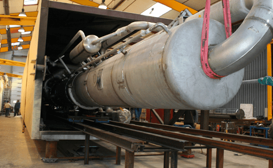
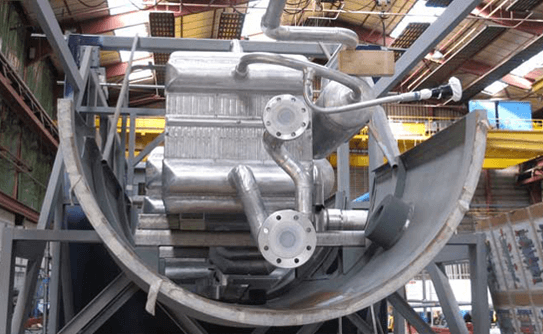
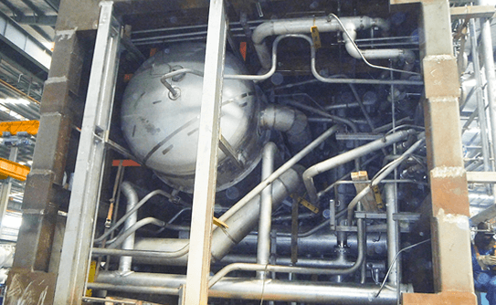
Description
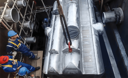
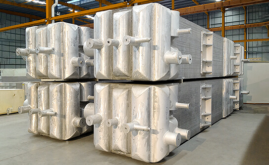
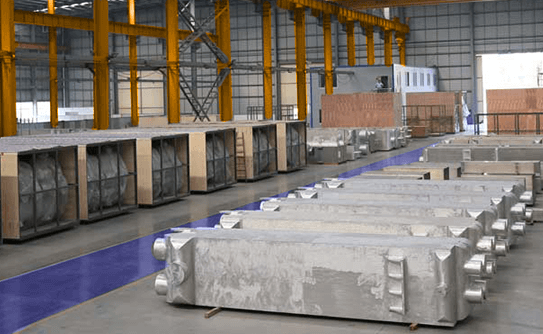
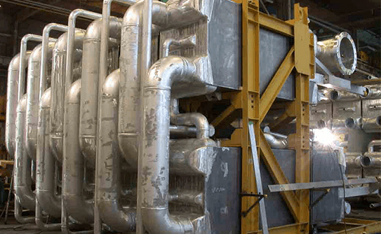
The heart of an air separation plant is the cold box, consisting of the following main equipment that operate under extremely low temperature conditions:
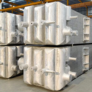
– Main Heat Exchanger (MHE),
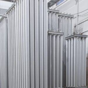
– Lower Column or Distillation Tower
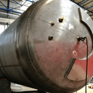
– Condenser/Re-boiler Vessel
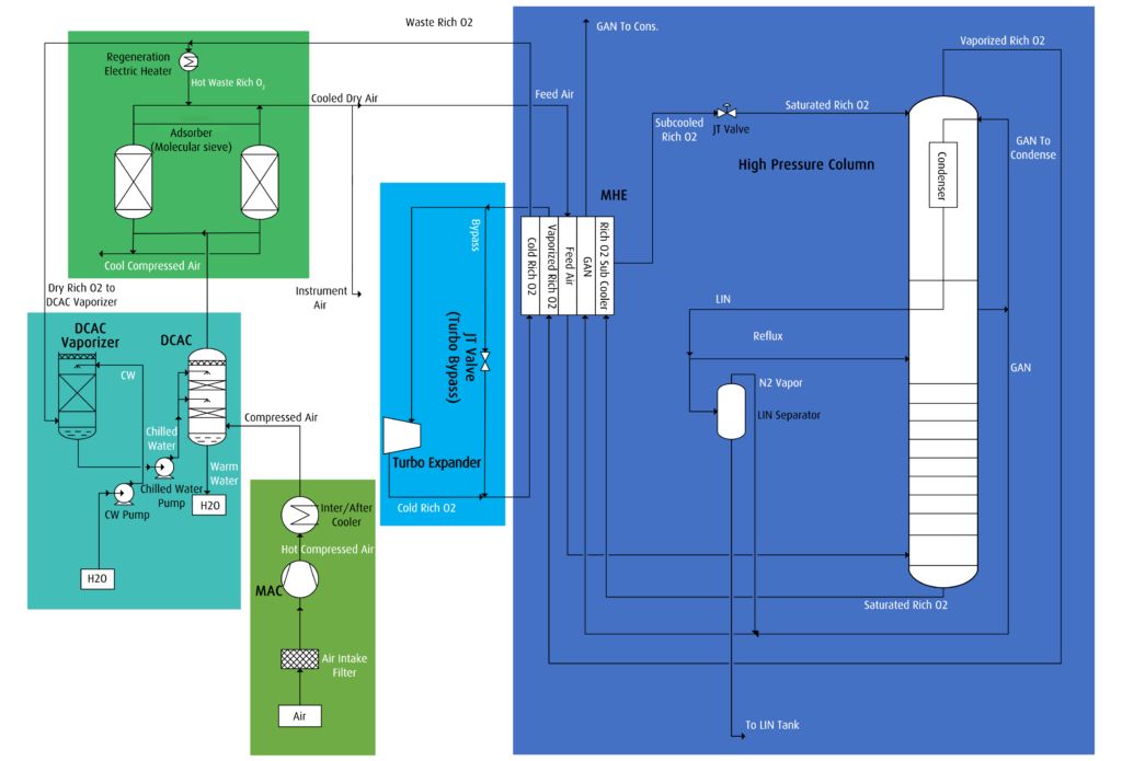
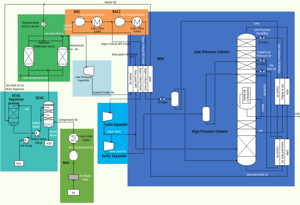
Dry compressed air is entered into the cold box and first cooled in the MHE until it reaches the dew point temperature. The resulting stream is then directed to the bottom section of the distillation tower.
The principle of separation utilized in this process is based on distillation, which involves both evaporation and condensation. Components with lower boiling points are evaporated while those with higher boiling points condensed in the gas phase. By repeating this process cycle, further separation of the air components is achieved.
Based on the principles of separation in distillation towers, the air components are transformed into pure nitrogen at the top of the column and oxygen-rich liquid at the bottom. The oxygen-rich liquid air is come from the bottom of the distillation tower and then sent to the condenser/re-boiler vessel (kettle) through an expansion valve. The cooling required for liquefying nitrogen gas, which serves as the product and also ensures reflux in the tower, is obtained through heat transfer between nitrogen and oxygen-rich liquid air. This heat transfer takes place in the vessel (kettle) filled with oxygen-rich liquid air in the condenser/re-boiler.
To cover heat losses and supply the necessary cooling, all or part of waste N2 which evaporated from heat transfer in the condenser/re-boiler is expanded in a turbo expander and then exits the cold box after passing through the main heat exchanger (MHE) passages. This waste N2 can be used to regenerate molecular sieves in the dryer package or to cool water in the water-cooling tower system. Any excess waste N2 is vent into the atmosphere.
Finally, pure nitrogen gas from the top of the distillation column is delivered to the MHE, where it is heated and ultimately provided to the consumer as gaseous nitrogen (GAN) with the desired purity. Pure liquid nitrogen (LIN) is also exit from the condenser/re-boiler vessel and stored for future use in a storage tank.
Block Diagram of the O₂ & N₂ Production Plant
Block Diagram of the N2 Production Plant